20w Power Amplifier Circuit Diagram. From the tool side you need a 50w weller soldering station with small tip thin solder wire tweezers. El34 operate with negative voltage in the grid 5.
Effect on received signal through loss with amplifier being placed across signal path. 4 thoughts on 20w power tube amplifier with el34 alexsander bittencourt vieira november 13 2014. Does tda 2040 need a pre amp i want to connect to dth audio output sattelite reciever i have build a circuit but there is no sound yet do i need 2200 or 220micro f to my speaker pls reply thnks.
20w mosfet power amplifier circuit with ifr9520 ifr520 20w power amp mosfet another approach is to connect two mosfets as a complementary drain follower the alternating output current provided by the mosfets is limited by the level of the supply voltages and the saturateion voltages of t3 and t4 resistor r8 together with r9 provides feedback for both the opamp and mosfets.
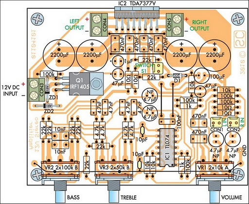
20w mosfet power amplifier circuit with ifr9520 ifr520 20w power amp mosfet another approach is to connect two mosfets as a complementary drain follower the alternating output current provided by the mosfets is limited by the level of the supply voltages and the saturateion voltages of t3 and t4 resistor r8 together with r9 provides feedback for both the opamp and mosfets. The circuit above is complete circuit contains tube amplifier circuit diagram and power supply circuit diagram. Links to data sheets. 20w stereo amplifier circuit diagram with a 12v supply the largest voltage swing a conventional solid state power amplifier can generate is 6v.
