4 1 Audio Amplifier Circuit Diagram. Describe typical input correction circuits. The base of the first common emitter bjt receives the ac signal input.
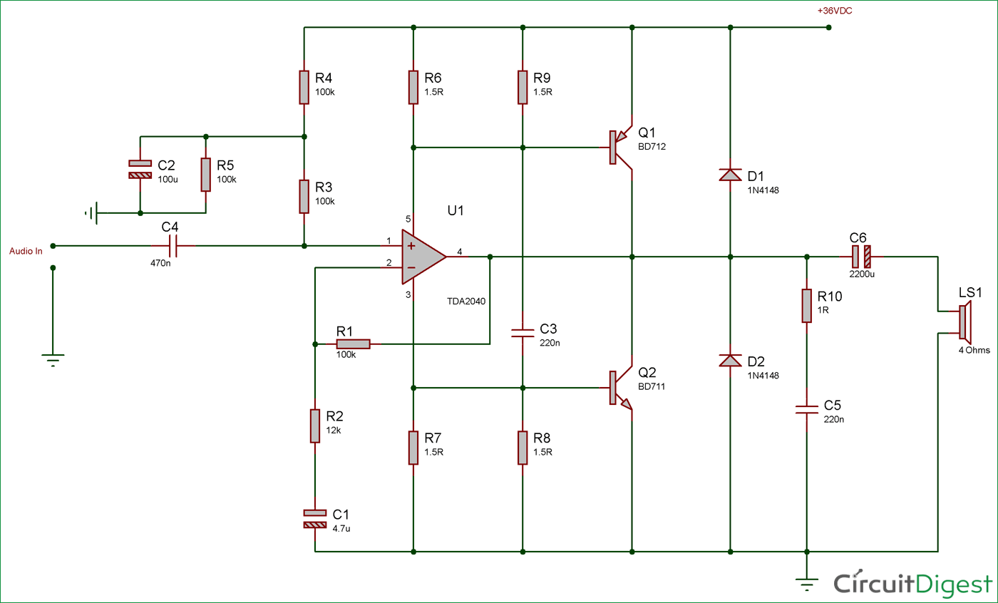
40 Watt Audio Amplifier Circuit Diagram Using Tda2040 And Transistor Pair from circuitdigest.com
Normally this is. Recognise the need for changing the shape of an amplifier s frequency response. If you need exactly 6 you can play a round with the resistance on the input.
The most used ics are tda2030 and tda2003 for small audio amplifiers kits and tda7294 for higher power amplifiers.
About the circuit diagram for 4 1 channel amplifer the circuit discussed in this blog is based on a class ab type amplifier and is powered using single supply. Normally this is. Describe typical input correction circuits. For splitting the signal you can use resistors for basic splitting.