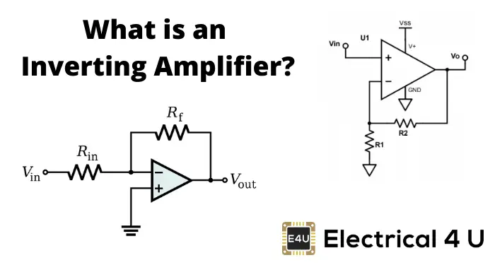
Circuit Diagram Of Inverting Amplifier Using Op Amp. Closed loop gain given by this circuit is r2 r1 when this ratio is small compared with the amplifier open loop gain and it s called as inverting circuit. Rf and rin together determines the gain of the amplifier.
No current flows into the input terminal and that v1 always equals v2. An operational amplifier often op amp or opamp is a dc coupled high gain electronic voltage amplifier with a differential input and usually a single ended output. In this configuration an op amp produces an output potential relative to circuit ground that is typically 100 000 times larger than the potential difference between its input terminals.
Generally a basic operational amplifier consists of two input terminals in which one acts as an inverting terminal and the other is a non inverting one.
Schematic circuit diagram op amp as an inverting amplifier proteus simulation. Op amp inverting amplifier using single ended supply. And another input terminal is grounded. Same as like before we use two external resistors to create feedback circuit and make a closed loop circuit across the amplifier.
