Circuit Diagram Of Transformer Coupled Class A Amplifier. Class a circuit instead of capacitor coupling a transformer coupled class a amplifier may be used to ac couple amplifier stages while providing dc isolation between stages. The figure below shows the circuit diagram of transformer coupled amplifier.
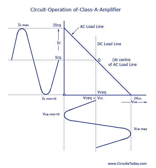
Here we will be discussing transformer coupled class a amplifier a form of class a amplifier having a maximum efficiency of 50 uses a transformer to couple the output signal to the load as shown in the below figure. The resistance of the transformer windings is normally very small so that there is no effect on the transistor bias conditions. Output characteristics of class a given by following diagram.
Now when we apply an ac input signal to base of the transistor the base current changes sinusoidally above and below the quiescent base current ibq.
The term single ended denoting only one transistor is used to distinguish it from the push pull amplifier using two transistors. The resistance of the transformer windings is normally very small so that there is no effect on the transistor bias conditions. An amplifier where the load is coupled to the output of the transistor using a transformer is called a direct coupled amplifier. In order to minimize those effects the transformer coupled class a power amplifier has been introduced.
