Class C Power Amplifier Schematic Diagram. This project will introduce two common power amplifier topologies and also illustrate the figure 2 shows the class ab amplifier schematic. Many power amplifier circuit diagram with pcb layout.
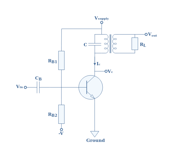
In this article class c power amplifier circuit is designed stimulate using orcad capture. As a result the transistor will start conducting only after the input signal amplitude has risen above the base emitter voltage vbe 0 7v plus the downward bias voltage caused by rb. This is linear power amplifier 2000 watt which need advance knowledge in electronics since the schematic diagram is very complex for hand made circuit i think you have to re design the schematic diagram using circuit diagram software designer such as diptrace eagle expresspcb ect.
The class c power amplifier is one kind of amplifier where the transistor conduct for less than 180 one half cycle of the input signal and its typical value is 80 to 120.
You can choose 0 5w to 1 200w. Class c power amplifier schematic below is a schematic diagram of a class c power amplifier. So easy to builds. Technical article designing a self biasing class c amplifier january 18 2018 by robert keim this article part of aac s analog circuit collection explores a self biased class c stage that could be used in an rf power amplifier.
