Draw The Circuit Diagram Of Non Inverting Amplifier. The non inverting amplifier configuration is one of the most popular and widely used forms of operational amplifier circuit and it is used in many electronic devices. This preview shows page 4 12 out of 47 pages.
Non Inverting Operational Amplifiers Working And Applications from www.electronicshub.org
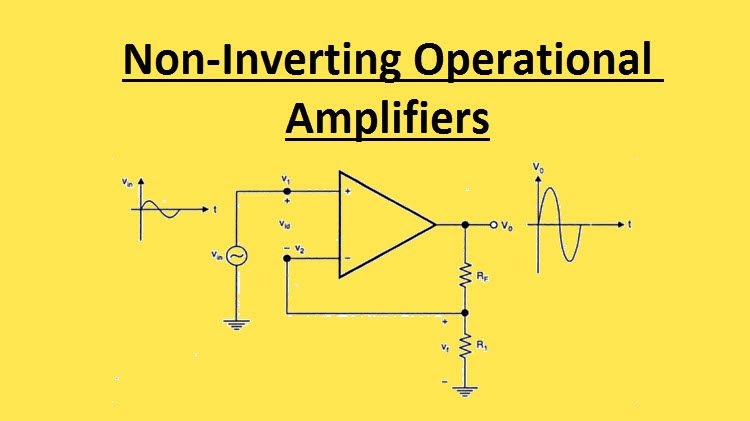
Due to the virtual ground concept the inverting terminal of op amp is also appears to be at the same potential vin. The following circuit diagram shows the non inverting amplifier using op amp. B determine a suitable resistor for r f if r 1 1kω in the question we are told that the gain needs to be 100 so we now apply the gain formula as shown below.
The following circuit diagram shows the non inverting amplifier using op amp.
Assume current i is flowing through the feedback resistance rf. In the op amps there are three basic terminals among those three two will be the input terminals and one is for output consideration. Gain 1 r f r 1 100. The following circuit diagram shows the non inverting amplifier using op amp.