Explain Instrumentation Amplifier With Circuit Diagram. A circuit providing an output based on the difference between two inputs times a scale factor is given in the above figure. So the value of r and rg decides the gain of the amplifier.
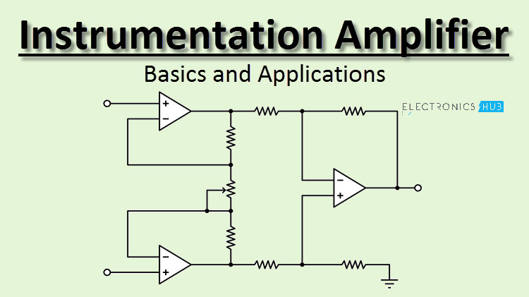
In the circuit diagram opamps labelled a1 and a2 are the input buffers. So the value of r and rg decides the gain of the amplifier. Additional characteristics include very low dc offset low drift low noise very high open loop gain very high common mode rejection ratio and very high input impedances.
The op amp 3 is a difference amplifier that forms the output stage of the instrumentation amplifier.
Circuit diagram advantages and applications an instrumentation amplifier is one kind of ic integrated circuit mainly used for amplifying a signal. Rg gain resistor. So the value of r and rg decides the gain of the amplifier. The op amp 3 is a difference amplifier that forms the output stage of the instrumentation amplifier.
