Feedback Amplifier Diagram. The block diagram of the current series feedback amplifier is shown below by which it is apparent that the feedback circuit is located in series by means of the output as well as the input. The sample of output voltage is applied as a input to feedback network which feeds back the output signal to the input.
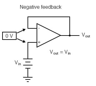
Barkhausen criteria state the two conditions to achieve sustained oscillations. So the signal achieved at the output of the feedback amplifier is given as. Negative feedback is frequently used in amplifier circuits as positive feedback causes excessive distortion in the circuit which we will discuss later.
Barkhausen criteria state the two conditions to achieve sustained oscillations.
A v s v o 1 a β therefore v o v s a 1 a β. Feedback amplifier using transistors circuit diagram. The difference of input signal and feedback signal gets amplified by the resistance amplifier. Voltage shunt feedback voltage sampling shunt mixing.
