Inverting Summing Amplifier Circuit Diagram. A non inverting summing amplifier circuit with three inputs are shown above. The voltage that is applied at the inverting terminal its potential value will be the same as that of the potential at the non inverting terminal.
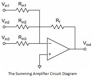
A non inverting summing amplifier circuit with three inputs are shown above. These input signals are given to the inverting terminal of the operational amplifier using input resistors like ra rb and rc. Inverting amplifier circuit diagram the output signal that is generated due to this amplifier is that will be of angle 180 degrees out of phase in comparison to the applied input signal.
The voltage inputs va vb and vc are applied to non inverting input of the opamp.
The output voltage of the circuit is governed by the equation. The output voltage of the circuit is governed by the equation. A non inverting summing amplifier circuit with three inputs are shown above. The voltage inputs va vb and vc are applied to non inverting input of the opamp.
