Lm324 Ic Amplifier Circuit Diagram. The properties of frequency response time from 0 hz to 200 khz the r1 10ohm and c1 0 01uf are for control of isolates within and r is the 10 ohms to control the flow of the op amp for each mean much. The components required for this circuit are lm324 op amp chip two 10kω resistors four 100kω resistors 22kω resistor 220kω resistor 1μf ceramic capacitor 33 nf ceramic capacitor 10nf capacitor and 100k ω potentiometer.
The lm324 operational amplifier is the heart of the circuit. The four individual speaker or power amplifier is connected to four outputs derived by four internally op amp of llm324 shown in circuit diagram. The properties of frequency response time from 0 hz to 200 khz the r1 10ohm and c1 0 01uf are for control of isolates within and r is the 10 ohms to control the flow of the op amp for each mean much.
Each ic contains four totally independed opamps.
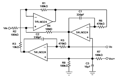
Lm324 ic based cell phone detector circuit diagram. The circuit is very simple to built using basic electrical and electronic components. Function generator circuit diagram with lm324 op amp the lm324 is a 14 pin integrated circuit the circuit diagram of the function generator with lm324 is shown below. The components required for this circuit are lm324 op amp chip two 10kω resistors four 100kω resistors 22kω resistor 220kω resistor 1μf ceramic capacitor 33 nf ceramic capacitor 10nf capacitor and 100k ω potentiometer.
