Loop Amplifier Circuit Diagram. For splitting the signal you can use resistors for basic splitting. On page 5 you ll find typical applications with several circuit diagrams.
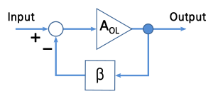
Any music as we know is in the form of a consistently varying frequency therefore when such a varying input is applied across the indicated c1 end terminals the same is delivered across the base t1 and ground. If you simply apply an input signal to the v terminal of an op amp the circuit is called an open loop amplifier. In this arrangement the voltage to be amplified is the same as the voltage of the v input.
In the open loop op amp circuit the v input is connected to ground and an input signal is placed on the v input.
The circuit is a simple two transistor pre amplifier using a feedback loop for enhancing the amplification. On page 5 you ll find typical applications with several circuit diagrams. You can choose 0 5w to 1 200w. In this circuit we can use 10 transistors.
