Multi Stage Amplifier Circuit Diagram. Carefully build this circuit on a breadboard or other convenient medium. Rarely is a pure common emitter configuration i e.
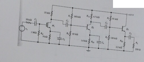
For instance when a circuit has n stages then the overall voltage gain is the product of all the individual stages present in the circuit. Explain what the purpose of the phase splitter circuit is and why it is necessary to properly drive the power transistors q 2 and q 3. Unlike complementary pair push pull amplifier circuits this circuit absolutely requires a preamplifier stage called a phase splitter comprised here by transistor q 1 and resistors r 3 and r 4.
Rarely is a pure common emitter configuration i e.
The input stage consists of transistors q1 through q7 with biasing performed by q8 q9 and q10. This amplifier circuit is a bit simplified from what you will normally encounter in practical multi stage circuits. The rationale behind a complementary pair cascade is a problem that can arise with a cascade of similar n type stages. For instance when a circuit has n stages then the overall voltage gain is the product of all the individual stages present in the circuit.
