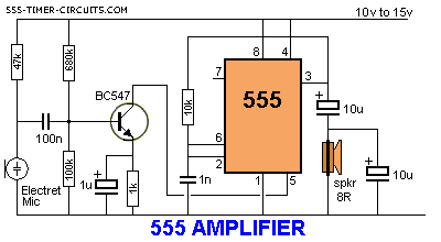
Ne555 Amplifier Circuit Diagram. Control pin 5 of 555 has been used here which is generally kept grounded through 01uf capacitor. Ne555 and ne556 applications an170 1988 dec 2.

Datasheet pinout circuit diagram inside. The audio amplifier circuit is shown in above diagram. Circuit diagram working principle.
Circuit diagram and explanation.
See basic stable multivibrator free running or square wave oscillator circuit. Ne555 and ne556 applications an170 1988 dec 2. Also the frequency and duty cycle are controllable using a capacitor and a variable resistor network. But in this circuit it is used as an audio amplifier the circuit is very easy to build using few components.