Positive Feedback Amplifier Circuit Diagram. Open loop configuration the basic comparator circuit is an op amp arranged in the open loop configuration as shown on the circuit of figure 1. When the feedback circuit is allied in series through the o p as well as the input then both the o p impedance the i p impedance will be increased.
Assemble the circuit on a good quality pcb. Positive feedback control of the op amp is achieved by applying a small part of the output voltage signal at vout back to the non inverting input terminal via the feedback resistor r f. Mosfet amplifier circuit 50 watts notes.
50 watts mosfet amplifier circuit diagram.
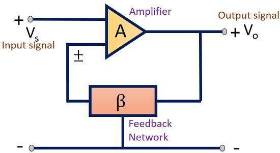
Other electrolytic can be 10 or 15v. 50 watts mosfet amplifier circuit diagram. If you need exactly 6 you can play a round with the resistance on the input. The block diagram of the current series feedback amplifier is shown below by which it is apparent that the feedback circuit is located in series by means of the output as well as the input.
