Rf Amplifier Circuit Diagram. Since this type of amplifier is normally used in rf application the capacitors can be much smaller in value than those used at audio frequencies. This is a 2 meters 144 mhz rf amplifier wich works in push pull and is build with.
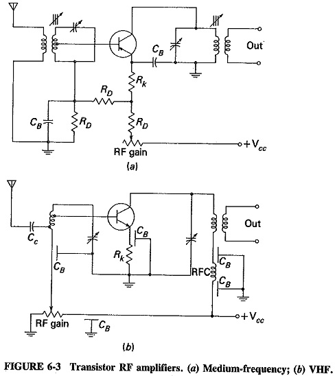
Browse through a total of 15 radio amplifiers electronic circuits and diagrams. 2m 144mhz push pull amplifier dv28120t p. The rfc acts as high impedance for the rf frequency itself so that it does not enter the bias supply.
Here we will learn the basics of rf module and how to use it as a standalone rf transmitter and receiver.
This amplifier has vhf very high frequency and uhf ultra high frequency response you can use it for receiver booster for example. Resources listed under amplifier category belongs to amplifiers main collection and get reviewed and rated by amateur radio operators. The rfc acts as high impedance for the rf frequency itself so that it does not enter the bias supply. Many power amplifier circuit diagram with pcb layout.
