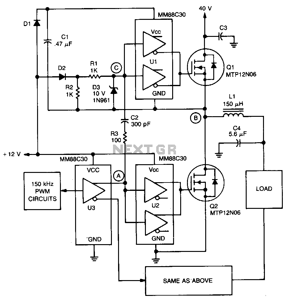
Servo Amplifier Circuit Diagram. Synchronizing transistors schematic circuit diagram. This circuit is designed to give pwm pulse width modulation signal output by using this different duty cycle pwm pulse we can control the servo motor.
Disconnect the cable from the cooling fan. This circuit is designed to give pwm pulse width modulation signal output by using this different duty cycle pwm pulse we can control the servo motor. Tda7293 100w rms amplifier schematic circuit diagram.
If you need exactly 6 you can play a round with the resistance on the input.
The low time will be 40 5 ms. You can choose 0 5w to 1 200w. If the fan does not operate correctly measure the voltage it receives. L2 and l3 of the servo amplifier in order to configure a circuit that shuts down the power supply on the side of the servo amplifier s power.
