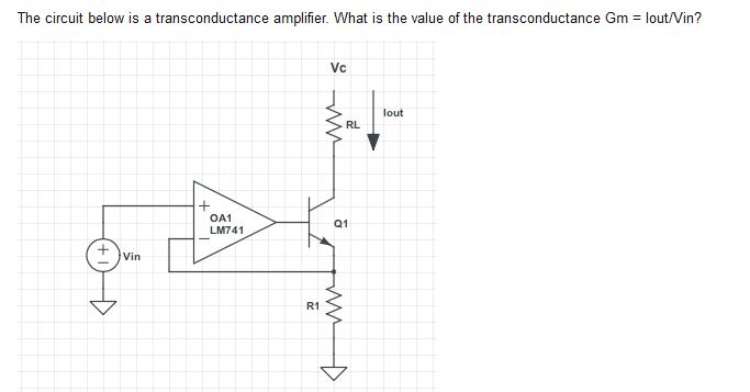
Transconductance Amplifier Diagram. 3 1 current feedback amplifier cfb combining a transconductance amplifier with a buffer and then adding negative feedback produces the architecture of a current feedback cfb amplifier. Cmos transconductance amplifiers architectures and active filters.

To design a 2 stage single ended op. One operational transconductance amplifier 7 3 feature description 7 3 1 circuit description the differential transistor pair q4 and q5 form a transconductance stage in that the ratio of their collector currents is defined by the differential input voltage according to the transfer function. The operational transconductance amplifier or ota as it is normally abbreviated is primarily used as a controlled gain block.
3 1 current feedback amplifier cfb combining a transconductance amplifier with a buffer and then adding negative feedback produces the architecture of a current feedback cfb amplifier.
Typical cfb amplifier block diagram. Cmos transconductance amplifiers architectures and active filters. Tance amplifier that can be paralleled with replicated units. Figure 6 shows a typical cfb block diagram.