Two Stage Rc Coupled Amplifier Circuit Diagram. Measure the voltage at output of first stage. The emitter bypass capacitor c e connected at the emitters of transistor q 1 and offer low reactance path to input ac signal.
Operation of rc coupled amplifier when an ac input signal is applied to the base of first transistor it gets amplified and appears at the collector load r l which is then passed through the coupling capacitor c c to the next stage. From the readings calculate voltage gain of first stage second stage and overall gain of two stages. Apply input by using function generator to the circuit.
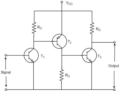
The figure below shows the circuit diagram of rc coupled amplifier.
The emitter bypass capacitor c e connected at the emitters of transistor q 1 and offer low reactance path to input ac signal. The rc coupled amplifier circuit may consists of various types of transistor configurations connected with the resistors and the capacitors. Two such amplifiers are connected in cascade resultant. The resistor r 1 r 2 r e and capacitor c e form biasing and stablization network.
