Thermocouple Amplifier Circuit Diagram. The three 22mω resistors will provide full scale output if the thermocouple opens. The op07 is in a non inverting amplifier so as not load the mv of thermocouple the zeners are to protect circuit if junction contacts heaters or the earth gets broken.
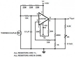
Previous 16 bit high accuracy. The max420 is operated at a gain of 191 to convert the 52 p vi o c output of the type j thermocouple to a 10 mv â c signal. Above circuit design is thermocouple amplifier circuit using ca3193 operating amplifier.
The ca3193 is an excellent choice for use with thermocouples.
The focus is on common op amp circuits so that the reader can quickly convert this material the following are examples of thermocouple junctions on a pcb. Previous 16 bit high accuracy. A thermocouple is a terrific way to measure temperature. The circuit is built around microcontroller pic16f877a ic1 precision thermocouple amplifier ad8495 ic2 k type thermocouple connected at con3 16 2 lcd lcd1 single changeover relay rl1 and a few common components.
